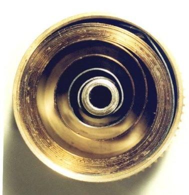
When replacing a clock mainspring, the repairman usually finds the closest match in his supplier's catalog to the mainspring being replaced. Frequently this may be incorrect because it may be too strong or too weak, or of an incorrect length. The best way to determine the correct mainspring is to build up a database of mainspring data: record the information about the mainspring and the clock for each clock that you overhaul. By the time you have fifty clocks recorded, you will develop an idea of what strength of spring is suitable for what type of clock, when a spring is too powerful and should be replaced with a weaker one, or vice-versa. In general, the strength of a spring is proportional to the cube of the thickness: if you double (2) the thickness, the spring is eight (=2x2x2) times stronger. The width is directly proportional to the strength: if you double the width, you double the strength. This assumes, of course, that the steel and the temper are the same in both springs being compared, which cannot reliably be ascertained, but we can at least use this information as a guideline at the bench. Below is a chart that you could use, showing the relationship between thickness and strength of two otherwise identical springs. When the relationship is expressed in percentages, it could be applied to any situation.
This is the formula to use to determine the correct mainspring length:
|
where L is length, T is thickness, r(a) is the arbor radius (half the diameter of the arbor), and r(b) is the barrel radius (half the inner diameter of the barrel). This formula could be entered into a computer spreadsheet as:
|
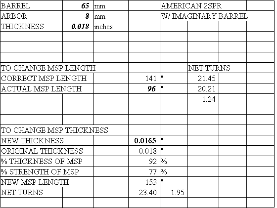
Below is also a spreadsheet that you could download and use for yourself. If you enter the dimensions, it would give you the answer. The diameter of the barrel and the diameter of the arbor are measured in millimetres and should include an allowance for the barrel hook and the arbor hook. The thickness of the spring is measured in inches because the suppliers do not all list the thickness in millimetres. This is confusing, but I have had to learn to live with it. Enter the data into cells B1, B2, and B3.
The correct mainspring length that you want will appear in cell D8. The number of turns you could get from the fully unwound position to the fully wound position is given in cell F8. This figure is theoretical: in practice, the net turns is one to two turns fewer, depending on the thickness and the condition of the spring. A thin spring may be less than one, as opposed to two for a very thick spring. A poorly finished spring or one in very bad condition may yield as much as a full turn less than an otherwise identical new one: this can be used to diagnose the condition of a spring once you build up your database.
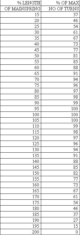
If your mainspring is not of the same length as the theoretically correct mainspring, you could compare the difference in the net turns, shown in cell F10, in order to decide whether to replace the spring. Also below, you will find another chart showing the length and the net turns. I was surprised to find that using a spring that was 50% too long (or 150%) resulted in a loss of net turns of only about 18%! It makes sense therefore to install a mainspring slightly longer (say by 10%) than the correct length you calculated because if the end were ripped off in the future, the next repairman could make a new hole and still have the correct length.
If you wish to install a spring of another thickness, enter the desired thickness in cell D14. You could then compare the new correct length for the spring in cell D18 and the difference in net turns in cell E19. You could also compare the thickness and the strength in cells D16 and D17.
This spreadsheet can also be used for "open" barrels, as if the clock had a closed barrel. In this example, I show a typical American two-spring clock and imagine that it has a barrel 65 mm in diameter. The table shows that it should have a spring 141 inches long! This is much longer than the 96 inch springs we get from our suppliers, but we only lose 1.24 turns because of this. Since these springs are much too strong for most clocks, I considered a new thickness of 0.0165", which is 8% thinner (=92%), and 23% weaker (=77%, a moderate reduction in strength). If we used a 153" spring 0.0165" thick, we could get over three extra turns compared to a 96" spring 0.018" thick (compare cells F9 and D19). If a supplier sold a 0.0165" thick spring 153" long, I would use it!
One more point to consider. Suppose you have two identical clocks except that one has a recoil escapement and the other a Graham. The recoil needs much more power because of its inefficiency. Consider making the spring about 50% stronger, or 15% thicker. If you have two identical clocks but one has a long pendulum, it would require more power than the shorter one. Manufacturers make up for variations in quality control and variations in design by making the springs far more powerful than they need to be, which means that clocks wear out sooner than if they had the correct power. Two notorious examples are the typical American two-spring, like the Seth Thomas #89, and the new Russian submarine clock. A clock with the correct spring will fail when the lubricant fails. A very overpowered clock will run long after the lubricant has failed, grinding its way through the dirt, damaging the clock. While you do not want a spring with barely enough power to run the clock because it may fail to run a full week, you should consider one that is only moderately overpowered, say by 30%.
|
Below are a few examples of how I collect mainspring data. You might consider something similar that suits your needs for building a database of information.
|
Here is the spreadsheet you could use to calculate mainspring lengths. You should be able to download it into your computer and save it. This is a ZIP file and contains an MS Works 4.0 and an Excel 4.0 file (Win95) and looks like the chart below. The numbers in bold are where you enter your data.
|
|
Mainsprings for American Clocks
I am interested in finding a way to measure the force exerted by mainsprings, but have been unable to find one accurate enough to yield useful results. I applaud Mr. Boxhorn's effort in the January 1997 issue of the Clockmaker's Newsletter.
While I agree that many of the mainsprings on the market intended for American clocks are excessively powerful, I urge caution in dramatically reducing the applied strength when replacing one. The 0.014" spring may work well when new, but in a few years it may have problems as it loses some strength. There are many reasons why caution should be exercised. I will only mention three:
1: American clocks, such as the Seth Thomas #89 movement, have pivots in the upper end of the train, (fourth wheel, escape wheel, warning wheel, governor, and pallets), that can be as much as 50% thicker (or of even greater diameter) than pivots in most foreign clocks. Exceptions include large, higher grade European grandfather clocks, French Morbier clocks, and oriental reproductions of American clock movements. Bigger pivots result in more friction because a greater circumference of pivots passes by for every turn the gear makes, and this higher level of friction is exacerbated when the lubricant gets older and thickens and has a dragging effect on the turning pivot. Further, the binding effect caused by a floating particle contaminating the bushing lubricant is much greater as the particle becomes jammed between the pivot and the bushing wall in the worn portion of the bushing as the pivot continues to turn.
2: The typical American clock escapement is a strip recoil escapement, which makes no pretense of being efficient. More power needs to be applied to the pallets to make up for this inefficiency: I would suggest at least 50% more than for a deadbeat escapement. I came to this conclusion by comparing a typical early 19th C. British grandfather clock with a recoil escapement and a typical early 20th C. German grandfather clock with a deadbeat escapement and cable-driven weights. The British clock needs a much heavier weight for the time-train. The efficiency of the escapement depends on the angles of the pallets' impulse faces relative to the respective tangents off the circle made by the tips of the escape wheel teeth. These angles vary widely, and therefore so do the efficiencies of the escapements. Some excess power is necessary to overcome this.
3: Different pendulums have different power requirements. A short and light pendulum with a thinner suspension spring needs less power than a longer and heavier pendulum with a thick suspension spring. A heavier Seth Thomas 124 pendulum may stop when hung on an Ingraham high-beat clock that was intended to have a light pendulum. There is argument about how heavy a pendulum should be and what effect this has on accuracy. I expect this argument may never be resolved because these variables cannot be quantified. However, we can safely say that a heavier pendulum usually needs a thicker suspension spring to prevent wobble and more power from the escapement to keep it going.
I feel that point #2 above is the most critical, because so much power is lost in even the best-designed escapements.
Since there is so much unknown about the power requirement about a particular clock, manufacturers wisely choose to err in favor of some excess power to make up for variations in manufacture and for differences between movements. Repairmen should do the same.
Since there are some repairmen, however, who are intent upon using weaker mainsprings, the following information may help. Mr. Dan Henderson, a Senior Manufacturing Technology Engineer at 3M, shared with me a formula for springs. All other factors being equal, the strength of the spring is proportional to its width: in other words, if we double the width, we double the strength. Similarly, the strength is proportional to the cube (to the power of 3) of the thickness: if we double the thickness, the spring is eight times stronger (2x2x2=8).
|
where f is force (or strength), b is the base (or width of the mainspring), and h is the height (or thickness of the mainspring). This means that the 0.014 inch mainspring has 47% of the strength of the 0.018 spring. I would be very careful in replacing a mainspring with one that is less than half as strong as the former.
K in the above formula is a constant, or a number. It reflects other factors that affect the strength of the spring. These include the shape of the spring, the temper and composition of the metal, variations in thickness along the length of the spring, whether the spring is new or several years old, to name a few. Since it is very unlikely that two springs will be of the same temper, etc, this formula does not provide a precise measure of strength: it can, however, provide a guideline for a clockmaker comparing two springs that appear to be similar, such as two new mainsprings from the same manufacturer, but of different thicknesses.
Timesavers is now selling a new mainspring for American clocks, part number 18790. It is 3/4" wide, 0.0165" thick, and 96" long. By the above formula, we can approximate it to have 77% of the strength of a similar 0.018" thick spring. If you believe that the mainspring in your American clock is too strong, I recommend that you try this mainspring. I have used it several times. I feel that a more moderate reduction in power would be more prudent.
|
Clock and Watch Lubrication
By considering the distribution of frictional losses in a timepiece, the horologist could determine where a high viscosity lubricant is appropriate, and where thinner lubricants should be used because of low power.
In order to find the forces exerted onto each pivot in the gear train of a watch, very sensitive measuring equipment would be needed, much more sensitive than what I have available to me. By creating a mathematical model of the forces in a watch, however, I could get an idea of what happens.
I will reverse the normal order of this project by presenting the conclusion first, in order not to deter those who are intimidated by the math. You would, however, benefit much more by reading the entire project.
Many watchmakers and clockmakers make the mistake of using the same thin lubricant for the first and second wheels as they do for the escapement. When lubricating a watch or clock, consider using the following rule of thumb:
1) use a heavy lubricant for high-torque, low-speed applications (mainspring, 1st and 2nd wheel pivots), and
2) use a light lubricant for low-torque, high-speed applications (3rd, 4th, escape wheel pivots, balance pivots, escape wheel teeth, clock strike governor pivots, etc.).
Also consider climate: Swiss watch oils are formulated in the Swiss Alps, and even most clock oils are almost as thin as water, at least in warm climates. While clock and watch oils have some thickness in colder climate conditions, they are very thin and less effective in warmer climates. We are not told to use different oils for timepieces intended for use in the cold Alps than for use in the hot desert.
Most if not all of my customers live in homes that today have climate control, so clocks in these homes do not get cold in the winter. Clocks that are not intended for use outside should be lubricated with thicker lubricants than those you might use for a clock that does not benefit from climate control. Watches used under normal conditions and worn on the wrist should not be lubricated with ultra-thin lubricants that you might use to lubricate a watch for use in extremely cold conditions, climbing high mountains or diving in cold waters. Timepieces for expeditions to the North and South Poles are usually not lubricated at all! When considering how thick a lubricant to use, you need to determine the thickness of that lubricant at the coldest temperature that the timepiece would be subjected to.
Why use a thicker lubricant if the timepiece were to be used in conditions that would not require a thinner lubricant? Thick lubricants have higher boiling points and they vaporize less easily. Thin lubricants vaporize easily: I have experienced problems with thin oils that dry up prematurely. I have seen several different clock oils dry up after only three years, and particularly one very expensive synthetic clock oil that dried up after only two years. A lubricant that fails after only two years not only fails to lubricate (reduce friction), but also fails to protect against oxidation. Thicker lubricants also have better cohesive and adhesive properties: in plain English, this means that a thicker lubricant stays in its place better when applied to a bushing without spreading or running off. If you consider the main purpose of lubricants, the benefit of a thicker lubricant becomes obvious: to reduce friction by providing a film between the two rubbing metal surfaces that keeps the metals apart. A good lubricant adheres to each metal surface to create this film and is not squeezed out under pressure. A good lubricant is cohesive so that it will exhibit good capillary action that will keep it in its place. A thicker lubricant has larger molecules (a longer carbon chain in the case of petroleum-based lubricants) and therefore provides a thicker film that keeps the metals further apart and resists higher pressures. As lubricant molecules slide over one another, some resistance to movement is caused, which we call 'drag' and which increases with the thickness of the lubricant. In low-torque applications, drag can impair the performance of the timepiece if the lubricant is too thick.
A couple of years ago, I lubricated a 16-size Elgin watch with a tower-clock oil, since I am not afraid to experiment with my own timepieces. It worked very well indeed and kept very good time. When I lowered the temperature by 40º Fahrenheit (in the refrigerator), this watch kept much better time than I was expecting (about thirty seconds slower per day), and there was a small decrease in the amplitude of oscillation of its balance wheel. At about the same time, I overhauled a Swiss watch of similar size and lubricated it with a very expensive synthetic watch oil: two years later, the watch hardly runs because the lubricant appears to have dried up.
Use a heavier lubricant for high-torque, low-speed applications. Clockmakers should consider using a heavy oil or grease to lubricate the mainspring, the pivots of the great wheel and second wheel. When applying a grease, you should apply a film over the entire area of the pivot and also over the entire area inside the bushing before assembly, because a thick lubricant will not spread by itself. Watchmakers should consider using a heavier lubricant to lubricate the mainspring, the pivots of the barrel and centershaft and third wheel. The watch's winding parts should be lubricated with a heavier lubricant. One problem frequently encountered in automatic watches is wear in the rotor arbor and its bushing: a heavier lubricant should be used here because the rotor is relatively heavy.
Use a thinner lubricant for low-torque, high-speed applications. This includes the pivots of the fourth and fifth wheels and of the pallet arbor in watches and clocks, and also the impulse faces of the pallets and escape teeth in clocks.
Use a light lubricant on the balance wheel pivots and the impulse faces of the pallets and escape teeth in low grade watches, such as a 7-jewel pocketwatch, where a small sacrifice in timekeeping could reasonably be made in order to use a lubricant of longer durability. Use an ultra-light lubricant in these areas in high-grade watches, such as a 23 jewel Railroad watch, where precision timekeeping is a necessity, but be aware that ultra-light lubricants have a tendency to dry up in the short term. Use ultra-light lubricants in watches that are subjected to extreme conditions of low temperature.
Take a moment to consider over-powered clocks with recoil escapements (which require plenty of excess power, as much as 50% more than a Graham Escapement), versus a low power clock with a more efficient Graham Escapement, such as a Vienna Regulator clock. An over-powered recoil escapement should be lubricated with a heavier lubricant, particularly because of the enormous power losses in recoil. A low-power clock should be lubricated with a lighter lubricant in the escapement.
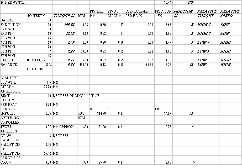
Consider a typical watch, in this case, a 16-size, 17-jewel pocket watch. Assuming that torque is proportional to the normal force on the gear's pivot, where a normal force is the force pushing the pivot against the bushing or jewel, in the direction of the force that acts upon that gear's pinion: if the torque that acts upon the 2nd wheel pivots were taken as 100%, the torque that acts upon the 3rd wheel pivots would be smaller by the ratio of the number of teeth on the 2nd wheel pinion and the number of teeth on the 2nd wheel, or 10/80 x 100% = 12.5%. Using ratios, a chart (see end) of percentage torque values could be created to show the relative torque values that act upon the pivots of each gear in the train, and also the pallet arbor pivots and the balance staff pivots. Using ratios, another chart showing the revolutions per minute (RPM) that each gear would make could also be made.
Using typical pivot diameter sizes for a 16-size watch, the circumference of each pivot could be calculated, each of which could be multiplied by the respective RPM value for that gear to find the amount of sliding that each pivot makes inside each jewel in one hour of operation, sliding that I refer to as 'displacement' in the chart (see end), as if each pivot were traveling a certain distance. A figure for each relative frictional loss could be obtained by multiplying each value of torque with each value of displacement or sliding. Each relative frictional loss could then be expressed as a percentage to reveal where the frictional losses really take place.
To find the RPM value of the pallet arbor pivots, take the degrees of rotation per beat, assumed here to be 18º (a high value), divide by 360º and multiply by 300 beats per hour to get 15 revolutions per minute. To find the RPM value of the balance pivots, multiply 300 beats per hour by the amplitude of oscillation of the balance wheel, assumed here to be 1.5 turns, to get 450 RPM.
If one third the torque of the escape wheel reaches the balance wheel, multiply the torque value for the torque that acts upon the pallets by 0.33.
Finding the frictional loss during impulse is more complicated, since this requires us to find the circumference of the escape wheel that is in contact with the pallet during impulse, neglecting the power lost during drop. Take the diameter of the escape wheel and multiply its value by pi to find its circumference. Find the circumference per beat by multiplying this by the degrees during impulse (10º) and divide by 360º. This value must be divided by the cosine of the impulse angle, which I have assumed to be 45º, to find the length of impulse, or 'distance traveled' during each impulse. Multiply this by 300 beats per minute to find the total length of impulse in one minute (the 'displacement per minute'), which you multiply by the torque acting upon the pallet to find a friction value.
The same method is used to calculate a value for the frictional loss in the fork horn and the roller jewel. The frictional loss is determined by the amount of sliding that takes place, which is assumed to be equal to the amount of depthing. I have assumed the depthing to be 0.07 mm. in this example.
The same method is used to calculate a value for the frictional loss during draw. The relative value of this loss is very small. The loss of efficiency caused by draw is mainly caused by angle, which we do not consider here, and not by friction. The loss by friction is relatively small and less than expected because it does not consider the total loss caused by draw.
The friction % values in the chart reveal nothing by themselves, but their relative values can be compared. The frictional losses in the pivots of the gear train are very small. The frictional losses in the pivots of the balance wheel are considerably more. Most significantly, the frictional losses in the pallets during impulse are very large because of two factors:
1) the 'displacement' during impulse is 85% more than the 'displacement' during the rotation of the balance wheel.
2) the torque during impulse is 2.75 times that which is exerted onto the balance wheel.
The results might tempt the watchmaker to lubricate the balance jewels and the escape wheel teeth only, leaving all other jeweled bearings dry (not a good idea!).
The values of torque show how much torque is exerted on the pivots of the first three gears in the train. It would make sense to consider lubricating these pivots with a heavy lubricant or even a grease as these high-torque, low-speed bearings would not suffer the effects of a heavy lubricant. The remaining pivots and friction surfaces are very low torque (less than 2% each). It would make sense to consider lubricating these pivots with a light lubricant as these low-torque, high-speed bearings would certainly suffer the effects of a heavy lubricant, which would cause drag.
The most important point to consider is that more power is lost in the transfer of power from the escape wheel to the pallets in a Swiss Lever type escapement. There are two power losses:
1) Power losses caused by angle. When the direction of the force exerted by the escape wheel onto the pallet is different to the direction of movement of the pallet (i.e. the direction in which the pallet receives the power), there is a loss of efficiency: in a correctly designed Lever Escapement the angle between the directions of the forces is 90º and the maximum achievable efficiency is only 50%. This power loss considers only angle and nothing else.
2) Power losses caused by friction. When the power is transferred in a 'rolling' action, as happens when the escape tooth rotates and provides an impulse to the impulse pallet of the balance wheel in a Chronometer Escapement, the transferor (escape tooth) and the transferee (impulse pallet of balance) appear to roll together, which results in an almost frictionless transfer of power. In the Lever Escapement, however, the escape tooth slides across the pallet's impulse face, causing a frictional loss that is determined by the magnitude of the impulse, the coefficient of friction of the two sliding surfaces and the displacement (or the amount of sliding that takes place during impulse).
By the way, note that in the Chronometer Escapement the direction of the forces is the same at the mid-point of the impulse, which means that this design experiences almost no power loss as a result of angle, in addition to almost no power loss as a result of friction (because there is almost no sliding taking place during impulse). The escape teeth of the Chronometer Escapement should not be lubricated.
The escape teeth of the Lever Escapement should be lubricated most carefully. Each tooth should be lubricated with a minute amount of lubricant because it should not be assumed that the lubricant would spread evenly over all the teeth otherwise. Since a light lubricant must be used, the watchmaker must be very careful not to lubricate in excess, as this might cause the lubricant to run, or be drawn away from the intended area.
As in any simplified hypothetical scenario, assumptions are made to simplify the problem and to overcome otherwise insurmountable or even unquantifiable problems.
This scenario does not consider the efficiency loss caused by the angle of the pallet impulse face because the loss caused by angle is not reduced with lubrication. The only efficiency loss that is reduced with lubrication is friction, and it is therefore only the frictional losses that are considered here.
It is assumed that the coefficient of friction is the same for all the friction surfaces, that all the pivots are in the same condition and that all the jewel surfaces are in the same condition (with no variations).
It is assumed that there is no frictional loss when the pivot shoulder rubs against the jewel, as if each jewel in the train were capped.
It is assumed that the masses of the gears, pallets and balance wheel have no impact upon friction. While the masses of the first four gears are of negligible influence upon the results, the masses of the escape wheel, the pallets and the balance wheel are significant. Their influence on the results is, however, ignored because their relative effects are unquantifiable. Of particularly significant impact is the mass of the balance wheel, which in a 16-size watch is relatively large, increasing the friction considerably as the balance pivots rotate in the jewels. In the hypothetical scenario, it is assumed that the balance wheel's torque percentage is equal to the impulse received by the roller jewel, which is probably an underestimation for a watch with a heavy balance wheel. Despite this problem, the results are still useful because its percentage of the total frictional loss in the watch would not reach the level of friction in the pallet impulse faces unless it were increased by six times. Increasing the value of friction of the balance wheel pivots would decrease the relative friction percentage values of the other friction surfaces but it does not change the conclusion (instead, it serves to reinforce the conclusion):
The two areas where the most power is lost in a watch are the balance pivots (in their jewels) and the pallet impulse surfaces and the escape teeth during impulse.
I believe that much more power is lost during impulse because of friction (in addition to losses caused by angle) than anywhere else in the watch. The watchmaker should pay most attention here.
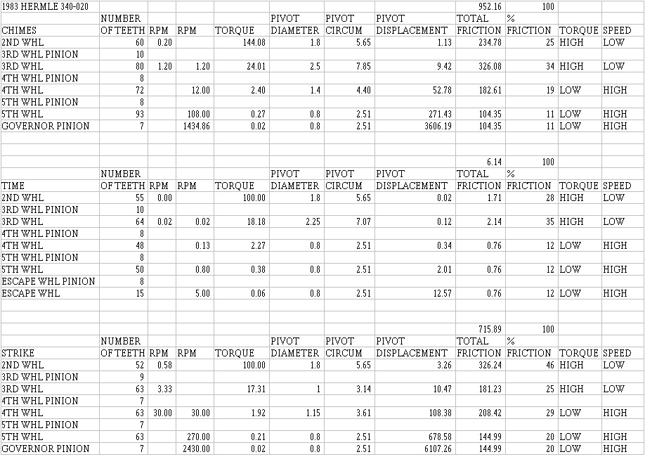
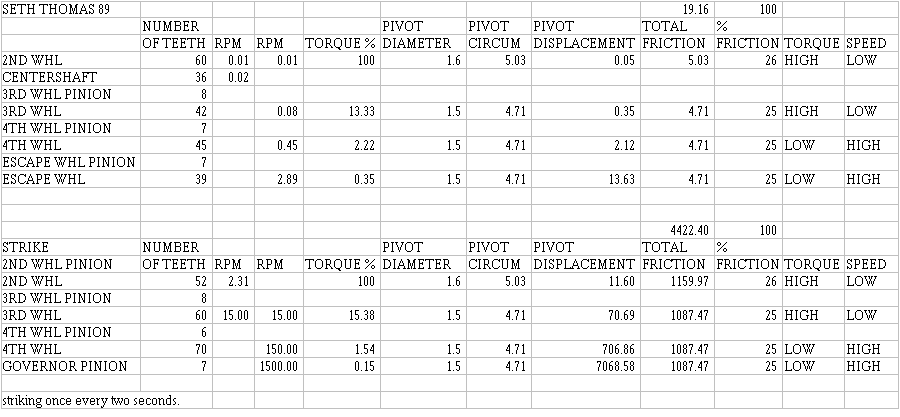
I am including torque calculation charts for two very common clocks so that clockmakers could see the relationships between the torque and RPM values for a typical American clock (a Seth Thomas 89) and a typical German chiming clock with a floating-balance (a Hermle 340-020). These differ from the watch chart in order to show how the friction is distributed in the gear train itself without considering the escapement: this information would be more useful to clockmakers. Notice how similar the friction percentage values are for the Seth Thomas clock. In the Hermle, the torque values have been adjusted to account for the stronger chime mainspring. These charts have two RPM columns to show that in the left column calculations were made up the column, and that in the right column calculations were made down the column. Observe how little torque the escape wheel receives: in the Seth Thomas, 289 times more torque acts upon the second wheel's pivots than upon the escape wheel's pivots. In the Hermle, 1650 times more torque acts upon the second wheel's pivots than upon the escape wheel's pivots.
Since thicker lubricants cause more drag, consider the bushings: a pivot turning in a longer bushing will be more affected by lubricant drag than one turning in a shorter bushing because of a larger area of lubricant film. However, using a longer bushing reduces the pressure on the bushing and the pivot because pressure is force divided by area. Most American clocks have very long pivots that protrude well beyond the bushing: in high-torque, low-speed applications, you might consider installing longer bushings that protrude beyond the plates, since longer bushings would be more durable, if the clock being repaired were not a high-grade work of engineering art and repair-as-art would not be called for. A mass-produced clock of lower grade, such as the Seth Thomas 89, would be well served by 3 mm bushings in the second wheel bushings. The bushings must not be longer than the pivots, however, so this could not be done to the Hermle clock's second wheels, for example.
Last, but not least, consider the difference in the rate of movement of the three trains of the Hermle movement. Most of the time, the clock neither chimes or strikes, but when it does, the gears move much faster. Looking at the chart below, you could see the effect this has on friction in the chime and strike trains. While looking at this chart, you will also see that there is more friction in the 3rd wheel pivots of the chime and time trains than in the 2nd wheel pivots: you would expect the reverse since more power acts upon the 2nd wheel pivots and since more wear takes place in the 2nd wheel bushings. If less friction takes place in the 2nd wheel bushings, you would expect less wear. This suggests that the increase in wear takes place not because of friction but because of something else: the yield pressure of the metal is exceeded, causing premature failure which we see as small pits in the pivot. The pressure on the pivot can be decreased by:
1) using a thinner mainspring (which we do not want to do in this case),
2) increasing the diameter of the pivot (the new Hermle 2nd wheels have slightly larger pivots),
3) replacing the pivots with a different metal that has a high yield pressure,
4) lubricating these pivots with a lubricant that has a very high yield pressure (that is, a very thick lubricant, a grease), keeping the metals apart so that this failure does not occur.
No lubricant lasts forever, so lubricating these pivots with a heavy lubricant would one day end in failure unless the clock were maintained before the lubricant fails. Since almost everybody uses their clocks until they will not run at all before they bring them in for repair, clockmakers should consider using a grease on the 2nd wheel pivots that has graphite: the magic of graphite is that it continues to work after the lubricant has failed! Either buy a lubricant with graphite added, or buy the graphite powder and mix some into the lubricant before applying it to the pivots and bushings. Many clockmakers do not like graphite because they think it is messy and makes the clock look ugly. The choice is yours, but I must say that I do not care much for a beautiful clock that does not work.
I have very carefully avoided recommending any particular lubricant or any particular brand of lubricant, as this is a very volatile issue. I have, however, had very unsatisfactory results with synthetic lubricants, and will never use them on my clocks or watches.
I would like to thank Dan Henderson for his suggestions. Dan is a mechanical engineer at 3M. He collects and repairs mechanical clocks and watches (and does not use synthetic lubricants). Many areas in this website would not have been possible without his suggestions!
A lot of work went into creating the charts below. I hope they are useful to you.
|
How Lubricants Work
|
An understanding of how lubricating systems work is crucial to the selection of a lubricant for a particular application. This essay could be summarized in one sentence: lubricants provide a protective film that separates the two rubbing surfaces and reduces the level of friction in the two rubbing surfaces.
Any surface contains irregularities, even when polished to a mirror finish. These irregularities may not be visible, except under a microscope. When two highly-polished surfaces are brought gently together, only some points on the surfaces will make contact. These contacts will be brought closer together when a force is applied at right angles to the surfaces (this force is referred to as a ‘normal load’), and the number of contact points will increase:
|
|
If a protective film were present on each of the surfaces, the surfaces could be separated:
|
The protective film must adhere to each surface in order not to be sheared off or pushed aside by the movement of the surfaces, particularly under a load.
The most commonly available lubricants today are manufactured from petroleum. A typical lubricant molecule consists of a long chain of carbon and hydrogen atoms, called an alkane:
|
An oil usually has between 15 and 20 carbon atoms. A grease has between 20 and 25 carbon atoms. The hydrogen atoms form very weak bonds with the surfaces. In the cases of brass and steel, metals consist of atomic nuclei surrounded by a sea of electrons. The hydrogen atoms are bonded to the carbon atoms by a pair of shared electrons, which face the carbon atoms: since there are no electrons on the other side of each hydrogen atom, the other side has a slightly positive charge because of the hydrogen nucleus. This positive charge attracts the hydrogen atoms to the sea of electrons of the metals. While the bonding is very weak, the total bonding caused by a large number of hydrogen atoms in a long carbon chain is considerably greater than in a short carbon chain. A shorter carbon chain could therefore be removed more easily by the force acting upon the surfaces. The forces that attract the molecule to the surface must be greater than the forces that attract the molecule to other molecules: this makes it possible to have the lubricant adhere to the surface yet easily slip over other lubricant molecules, and the level of friction is reduced by having lubricant molecules rubbing against one another rather than brass and steel surfaces rubbing together. This is as simple a description of lubrication theory as you would find anywhere!
Longer carbon chains get tangled together like spaghetti, thereby making the ability of the lubricant to flow more difficult. This is why lubricants with longer carbon chains are thicker than lubricants with shorter carbon chains.
A lubricant with a longer carbon chain is less volatile. As the temperature increases, the molecules vibrate more vigorously until the vibration causes the weak intermolecular bonds to break. As they break, molecules become free to float away or evaporate. Molecules with longer carbon chains vibrate less at a given temperature because they have more mass, so they are less likely to evaporate. Situations in which a lot of heat is generated, such as a car engine, require oils that will not evaporate easily. Bearings with slow-moving parts do not experience such levels of heat, so a different lubricant is required. A lubricant with larger molecules should be used to minimize evaporation, particularly on bearing surfaces that are subjected to high torque and low speeds (revolutions per minute). However, thicker lubricants can interfere with the action of the mechanism when applied to bearing surfaces that are subjected to very low torque and high speeds, so a thinner lubricant must be used, even though thinner lubricants are more likely to evaporate! The purpose of application is particularly important in selecting a lubricant because of the need to consider heat, torque and speed. If a shaft rotates very quickly in a bearing, the fast motion has the effect of bringing more lubricant into the bearing, called a hydrodynamic effect, which increases the separation of the rubbing surfaces. Slower-moving applications do not benefit from the hydrodynamic effect.
You will have noticed that water boils at 100º Centigrade: at 99º, it is a liquid; at 101º, it is a gas. Water freezes at 0º, again within a similarly narrow range of temperatures. Oils, however, solidify gradually as the temperature becomes colder, slowly becoming thicker and thicker until the oil no longer flows: oils solidify over much wider temperature ranges because oils are manufactured as blends of many different oil molecules mixed together to modify the lubricating and thickness properties of the combined mixture. There are many different compounds with the same number of carbon and hydrogen molecules, so while they have the same empirical formula, such as C18H38 .
Their structures are all different, as are their lubricating and thickness properties. Different compounds with the same empirical formula are called isomers. Lubricants can be prepared with blends of isomers as well as with blends of molecules of different lengths of carbon chain to further modify the properties of the combined mixture, which solidifies over a wider range of temperatures and becomes a solid at a lower temperature than an equivalent oil with just one type of molecule (one isomer). Chemical engineers can therefore prepare a lubricant suited for each application, or a lubricant suited for a wide variety of applications. This is called the Base Oil.
The major mineral oil components are paraffinic, naphthenic, and a smaller amount of aromatic compounds. Paraffinic oils are straight chain (as in the example above) or branched aliphatic hydrocarbons (in other words: alkanes and their isomers). Naphthenic oils have saturated hydrocarbons (alkanes) that have at least one closed ring of carbon atoms. Aromatic compounds have one or more benzene rings in each molecule. The variations in composition directly affect the lubricating properties of the blended mixture. Other chemicals are added to the base oil to improve the properties of the oil. Mineral oils react with oxygen at hot temperatures to form hyperoxides, followed by organic acids, which cause the formation of sludge and varnish and the corrosion of metal parts. Chemicals called oxidation inhibitors are added to the base oils to prevent the deterioration of the oil and the corrosion of metal parts. Similar chemicals called rust inhibitors are added to protect steel parts. Dispersants and detergents are added to help dissolve contaminants and sludge so that deposits are not formed. Other chemicals, such as anti-wear and anti-scuff additives, that are sometimes added to base oils, react with the metal atoms on the surfaces to form a protective layer that has a lower friction than that of the metals rubbing against each other.
Applications that involve higher levels of torque and slower speeds (obliviating the hydrodynamic effect), require lubricants that can adhere more strongly to the metal surfaces. With weaker bonding, the lubricant molecules can be sheared off by the action of the surfaces, and these molecules must be replaced immediately by other molecules. Stronger bonding can be achieved on metal surfaces by using a lubricant that has polarized molecules (at one end), such as a metallic soap like lithium stearate. The polarized end of the molecule is attracted to the metal surfaces while the long alkyl group forms part of the protective blanket that covers the surface. The metallic soap will have a lower melting point than a comparable but nonpolarized alkane because of much stronger hydrogen bonding between the polarized molecules, compared to the much weaker (van der Waals) intermolecular forces. The hydrogen bonding between the molecules also strengthens the protective blanket that covers the surfaces. If you buy an automotive wheel-bearing grease that says 'lithium base' on the container, it would probably contain lithium stearate or a similar lithium soap.
Graphite is an excellent additive because its layers of atoms slide easily over one another. Since graphite does not form bonds with the metal surfaces, it is easily lost: mixing the graphite in base oils makes it possible to lower the friction level beyond the level achievable by the oils alone, and the oils act as carriers, or as a medium to contain the graphite.
Other lubricating techniques are used to separate rubbing surfaces, such as teflon coatings, which act as dry lubricants to minimize friction and the drag caused by liquid lubricants. The techniques are different, but the goals are the same: to separate rubbing surfaces and to minimize friction.
Synthetic lubricants are manufactured for specific purposes. These lubricants are not blended from natural oils, but rather produced artificially under controlled conditions to minimize levels of contaminants. By having more control over what goes into a lubricant product, chemical engineers hope to produce a superior lubricant: ideally, they want a thinner lubricant with a higher boiling point (and therefore low evaporation rate), no thermal breakdown of the oil molecules, and with higher lubricity (a measure of the extent to which friction is reduced).
Before the advent of the automobile, petroleum was used mainly for manufacturing kerosene for lamps. Most oil products were obtained from animal, plant and fish oils and fats. These natural oils tend to contain mainly alkenes (unsaturated hydrocarbons), so they differ with their alkane counterparts in that they have lower melting points: the same lubricity could be achieved with a thinner oil, assuming both oils being compared had the same number of carbon atoms. However, these oils tend to have fatty acids that must be neutralized. Alkenes are not as stable as alkanes, so they are more easily oxidized into fatty acids and they become more unstable when subjected to heat. These oils are not hostile to bacteria, which accelerate the deterioration of the oils, whereas mineral and synthetic oils have longer life expectancies. Fatty acids tend to corrode metal parts and also to result in the formation of sludge. Oils and greases for clocks and watches were (and many still are) made from fish oils, whale fat and porpoise oils being among the favourites. The new oils have additives that protect the oils from bacteria and oxidation, thereby extending their life expectancies considerably. The principles by which lubrication takes place are the same, as outlined above. Note, however, that even the new natural oils have essentially no tolerance for heat and must therefore not be used where heat is generated (such as electric clock motors). You must use a mineral oil for electric clock motors, such as a single-weight, non-detergent oil.
I hope this essay has made you a better-educated consumer of oils and greases for clocks, electric motors, cars, or anything else. It is only a brief overview of a few aspects of tribology that might be of interest to horologists. Tribology, or the study of lubrication, is a very wide field: the more you know, the more you know you do not know! I prefer petroleum-based mineral oils over any other, especially since the quality of mineral oils has improved to such an extraordinary extent in just the last fifteen years, thanks to the hard work of many chemical engineers! Most mineral oils manufactured and marketed in the United States by well known manufacturers are of very high quality indeed, and a statement that the oil meets government and manufacturer specifications is more reassuring still. However, you still must be cautious when selecting lubricants since some lubricants are poorly engineered and since many will not suit the particular application you wish to apply it to (the same is true of clock oils from your clock suppliers: the fact that it says ‘clock oil’ on the bottle does not mean that the clock oil you bought is of high quality or that it will provide adequate protection of the second wheel pivots, as it might for the escape wheel pivots). Consider these examples. There is a very expensive clock oil that I have had many problems with because it dries after about a year and a half. It is also very thin: it tends to run too easily when applied to bushings. There is another clock oil (the cheapest) that I have found to work very well: it was still liquid five years after I applied it to numerous clocks. Two of my suppliers told me that it is not a clock oil (even though it said ‘clock oil’ on the bottle) but rather a light machine oil: in other words, a highly refined mineral oil, similar to kerosene in appearance, consistency and smell. The only problem I have experienced with this oil is that it is too thin (at room temperature, here in Texas) and runs too easily when applied to clock bushings (but it has worked very well on my pocket watches). I have had disappointing experiences with three synthetic lubricants and therefore do not use them.
Now for the disclaimer to keep me out of trouble:
1. To lubricate a clock, use only an oil that says ‘clock oil’ on the bottle.
2. To lubricate an electric clock motor, use only an oil that says ‘oil for electric motors’ on the bottle.
3. To lubricate a watch, use only an oil that says ‘watch oil’ on the bottle.
4. To lubricate your car, use only an oil that says ‘car oil’ on the bottle.
5. Experiment at your own risk!
|
After the Lubricants Fail: Wear
This page addresses the issue of why clocks eventually fail. The essay about cleaning and polishing brass, in this website, describes the chemical properties of brass and steel and how oxidation takes place. The essays about lubrication describe the physical properties of lubricants and how they work. The essays about bushings describe how repairs should be performed. Together, these essays present a more complete explanation of issues related to clock repair and preventive maintenance.
Lubricants reduce friction in the bushings by adhering to the metal surfaces to form a film that separates the metals, and protect the metals against corrosion with the protective film. Lubricants fail for many reasons, the most common of which is evaporation in the case of clocks. Each clock bushing has only about a quarter to half a drop of oil. If the oil evaporates, nothing is left. Oil can also deteriorate because of the presence of bacteria, resulting in corrosive acids being formed (the oil becomes "gummy"). If the correct lubricants were used, very little wear would take place in the bushings. Most of the wear takes place after the lubricants have failed. Understanding how and why wear occurs in clock bushings provides insight into how best to repair the clock bushings and how to ensure maximum durability after the repair.
When a clock is repaired, all the pivots are polished to make their surfaces smooth and also to remove any layer of iron oxide on the surface. While the surfaces of the brass plates should not be polished, as described in the essay about cleaning and polishing brass, the surfaces inside the bushing holes must be cleaned and the oxide layer removed. A clean brass hole has a bright yellow colour on the inner surface when examined with a loupe. The presence of an oxide layer in the hole can be seen because the colour becomes brown or black.
To understand why the brass plates should not be polished, consider how stainless steel remains stainless:
"Stainless steel is an alloy of iron (Fe) and carbon (C). The carbon content is not greater than 2wt%. Stainless steel also contains chromium (Cr) which gives it corrosion resistance due to an oxide of chromium that forms on the alloy surface. The chromium content should be greater than 12wt% in order to give adequate protection."
The zinc in brass similarly forms a layer of zinc oxide on the surface of the brass, protecting the metal underneath the surface. The protective layer of zinc oxide should not be removed, unless another form of protection, such as lacquer, were applied.
To determine why wear takes place, consider the physical properties of the metals and the oxides in the bushings, rather than their chemical properties. The first physical property to consider is hardness. Many of the hardness values in the table at the bottom of this page are only approximate, but they are useful to determine several things:
1. Metal alloys are usually harder than the individual metals. Brass is harder than copper and zinc. Steel is harder than iron.
2. Metal oxides are usually harder than the metals. The best example is aluminium oxide, which is extremely hard. From the absolute hardness column in the table, however, you can see that the diamond is four times harder than aluminium oxide.
3. Copper oxide, zinc oxide and iron are of similar hardness. This means that these oxides, since they have crystalline structures, could scratch the surface of a soft iron pivot. High-carbon steel pivots, however, are considerably harder than these oxides. You would expect that steel pivots would be unlikely to be scratched by these oxides. However, even an oxide with less hardness, such as zinc oxide, could cause wear:
"Zinc oxide is abrasive and zinc in the copper matrix promotes galling when mated with steel."
The most important point to remember here is that the main cause of wear in a clock bushing is the presence of metal oxides. If the formation of oxides could be prevented, the bushings and pivots would last much longer.
4. A steel pivot, unprotected by lubricant, could form a layer of iron oxide if exposed to oxygen and humidity in the air. The iron oxide could become embedded in the surface of the brass bushing, scratching the steel pivot. When the surface of the pivot is scratched, iron is removed, which is more likely to become oxidized with oxygen from the air than the pivot itself, because the iron that is removed is in powdered form and has a much greater surface area than the iron in the pivot. Iron oxide is much harder than iron. Wear takes place at an accelerated rate. The oxide layer inside the bushing should be removed to make sure that no iron oxide is embedded in the surface.
To explain why iron oxide is important here, consider an extreme example: aluminium oxide, Al2O3, the second hardest mineral on earth, second only to the diamond, is much harder and more abrasive than iron oxide, Fe2O3. Many of the least expensive clocks have plates made of aluminium instead of brass. This means that the bushing surfaces are of aluminium and the pivots are of steel. Clocks with aluminium plates do not last long because of the formation of aluminium oxide. The combination of steel and aluminium has the added disadvantage of an electrochemical reaction between the dissimilar metals in the presence of an electrolyte (such as humidity, water), accelerating the formation of aluminium oxide and the subsequent deterioration of the bushing and the pivot. To prevent the electrochemical reaction, the lubricant in the bushing must separate the metals and protect the bushing from humidity and other contamination.
Another physical property to consider is structure. Hard crystalline structures have fractures with sharp points and edges. The hardest minerals, such as diamonds, aluminium oxide, and silicon carbide, with their sharp points and edges, are often used as abrasives. Aluminium oxide is often used to make sandpaper and emery paper. Consider what would happen if you introduced a few grains of sand into a clock bushing. Its presence in a clock bushing quickly results in failure. Sand is silicon dioxide, SiO2, another hard, crystalline mineral.
Aluminium oxide plays a major role in horology because virtually all jeweled clocks and watches have synthetic ruby jewels, made of aluminium oxide. Some high-grade timepieces also have diamond cap jewels. The surfaces of the ruby jewels are highly polished with diamond-impregnated polishing compound. When a ruby jewel becomes cracked, its sharp edges quickly damage the steel pivot. Thus the physical properties of the mineral are of paramount importance: as a highly polished surface, it has very low friction, but as a cracked surface or as a powder, it has very high friction and is extremely abrasive.
Bronze bushings are often used in electric motors because of the hardness and durability of the copper and tin alloy. These bushings are made of cast and heated (sintered) powdered bronze, which is porous. The porous nature of the bushing makes it possible to impregnate the bushing with a relatively large quantity of oil by submerging the bushing into hot oil. Bronze bushings for clocks, however, are not porous because they are made from bronze wire. The quantity of oil the clock bushing can retain is much smaller. When the lubricant fails, and especially if it evaporates, the bronze surface is exposed to air and a layer of tin oxide is formed. Tin oxide is even harder and more abrasive than iron oxide. This is why most clocks with bronze bushings that come in for repair have badly scored pivots. All bronze bushings in clocks should be replaced with brass bushings whenever possible.
Another question to consider is the durability of different clocks, why some pivots are more frequently scored than others. Many French clocks and other high-grade clocks have hard pivots made from high-carbon steel. When these clocks are repaired, they often have one or more badly scored pivots, and iron oxide is visible in the bushing. Comparing these clocks with American clocks of similar vintage (1850 - 1910), such as New Haven, Sessions, Seth Thomas, and Waterbury, a difference becomes clear. American clock pivots become rusted and scored less frequently. Bushings wear but the pivots are usually not badly damaged. The reason for this is simple. Unlike the expensive clocks, these American clocks were designed to be affordable, and their steel parts were made of mild steel dipped in molten zinc, called galvanized steel (the same material as the common nail). The zinc forms a thin layer of zinc oxide, protecting the metal underneath in the same way as it protects brass. The zinc becomes the sacrificial metal, protecting the iron. These American clocks were less expensive, more reliable, more durable, and easier to repair: this is obviously a winning combination.
I have simplified the explanations on this page by not mentioning the presence of other elements in the metals, either intentional (in the case of alloys) or unintentional (in the case of impurities). Aluminium clock plates are usually an aluminium alloy with added copper, manganese, or magnesium. Brass clock plates are made with copper (about 70%), zinc (about 30%), and lead (1%), but it may contain impurities, such as a small amount of iron. Lead is added to improve machinability (ease of cutting). Bronze is a copper (about 90%) and tin (about 10%) alloy, but it may also contain impurities, such as small amounts of lead, zinc, nickel, iron, sulphur, and aluminium. Involving the impurities would make the problem more complicated, but it should be mentioned that some impurities are present in every metal. Clocks made prior to the Industrial Revolution usually have higher levels of impurities in their metals because of older technologies used in the manufacturing processes. High levels of impurities often cause problems with quality control.
Knowing what causes wear suggests the importance of meticulously polishing the pivots and remove the oxide layer from the inner surface of every bushing. It also suggests what properties the lubricants should have, to separate the surfaces of the metals and to protect the surfaces of the metals from corrosion (caused by air and humidity). Since the best lubricants last about six years, every clock should be inspected carefully at least every five years and lubricated as needed.
| |
Mohs
Hardness |
Absolute
Hardness |
| Talc: Mg3Si4O10(OH)2 |
1 |
1 |
| Lead: Pb |
1.5 |
|
| Gypsum: CaSO4.2H2O |
2 |
3 |
| Tin: Sn |
1.5 |
|
| Zinc: Zn |
2 |
|
| Copper: Cu |
2.5 |
|
| Calcite: CaCO3 |
3 |
9 |
| Brass: copper and zinc alloy |
3 |
|
| Aluminium: Al |
3 |
|
| Bronze: copper and tin alloy |
3.5 |
|
| Fluorite: CaF2 |
4 |
21 |
| Copper oxide: CuO |
4 |
|
| Zinc oxide: ZnO |
4 |
|
| Iron: Fe |
4 |
|
| Apatite Ca5(F,Cl,OH)(PO4)3 |
5 |
48 |
| Lead oxide: PbO2 |
5 |
|
| Typical knife blade (steel) |
5.5 |
|
| Orthoclase: KAlSi3O8 |
6 |
72 |
| Iron oxide: Fe2O3 |
6 |
|
| Good steel file (high-carbon steel) |
6.5 |
|
| Tin oxide: SnO2 |
6.5 |
|
| Quartz: SiO2 |
7 |
100 |
| Topaz: Al2SiO4(F,OH)2 |
8 |
200 |
| Sapphire, ruby: aluminium oxide Al2O3 |
9 |
400 |
| Silicon carbide: SiC |
9.5 |
|
| Diamond: C |
10 |
1600 |
I would like to thank Dr. Hugo Steinfink (Chemical Engineering) and Dr. Harovel Wheat (Mechanical Engineering), from the University of Texas in Austin, for answering many questions I had about metal oxides, and for making suggestions about how best to find more information on the internet.
|
| Daniel's Double Independent Wheel Watch Escapement |
Cylinder Escapement
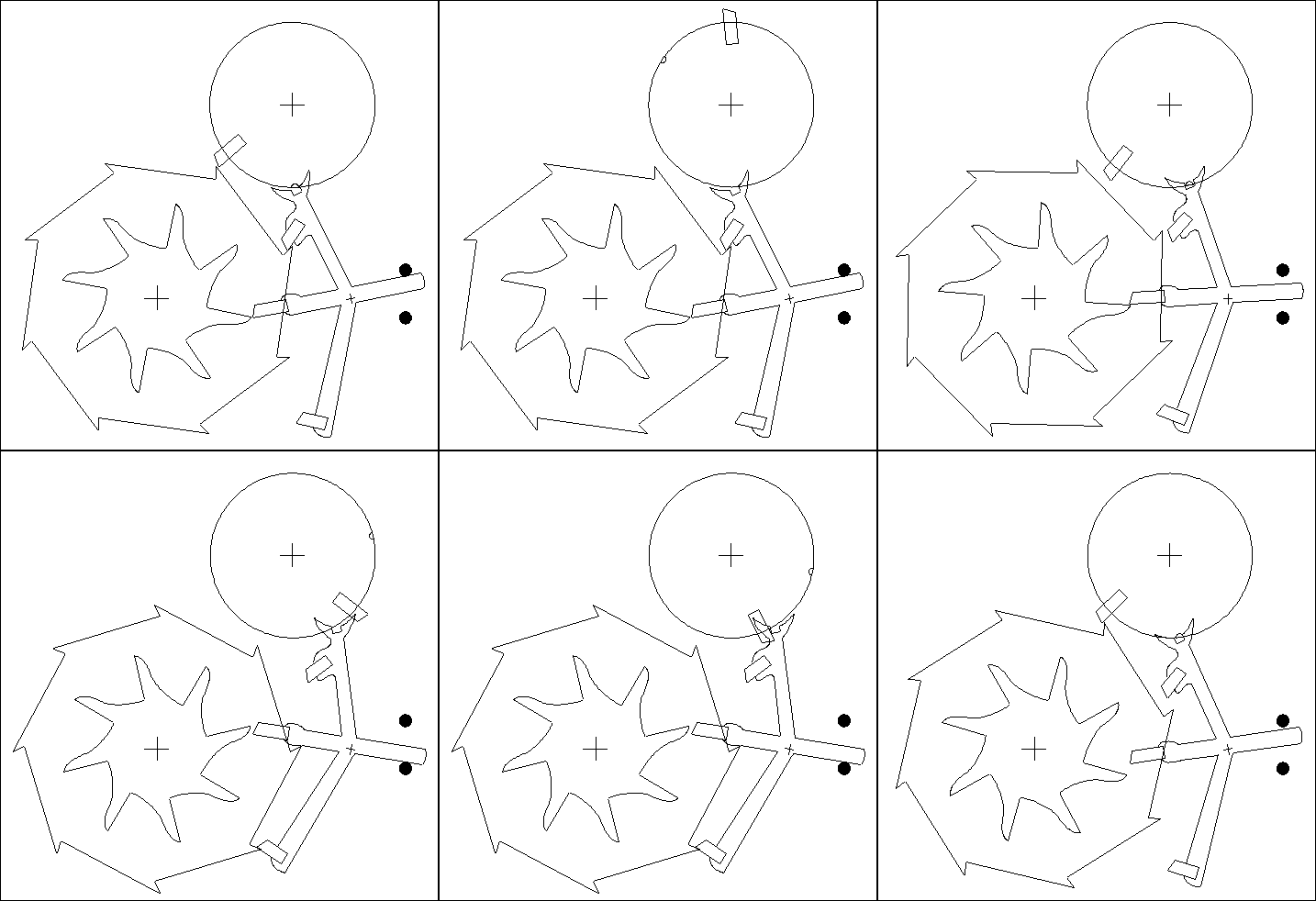
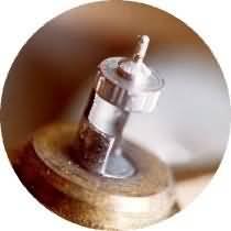
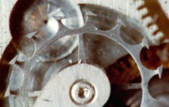
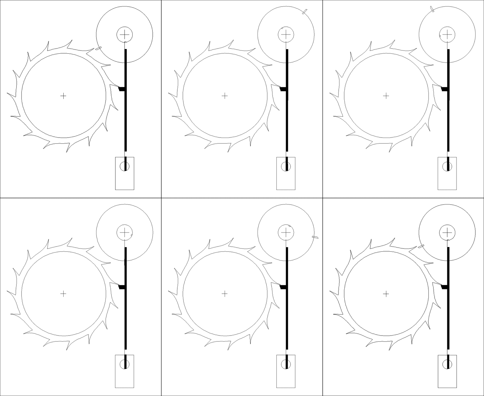
This animation would be difficult to understand if you did not know what the cylinder escapement actually looked like. If you would like to see enlargements of these photos, select the photo you would like to see enlarged, and the enlargement would open in a new window.
|
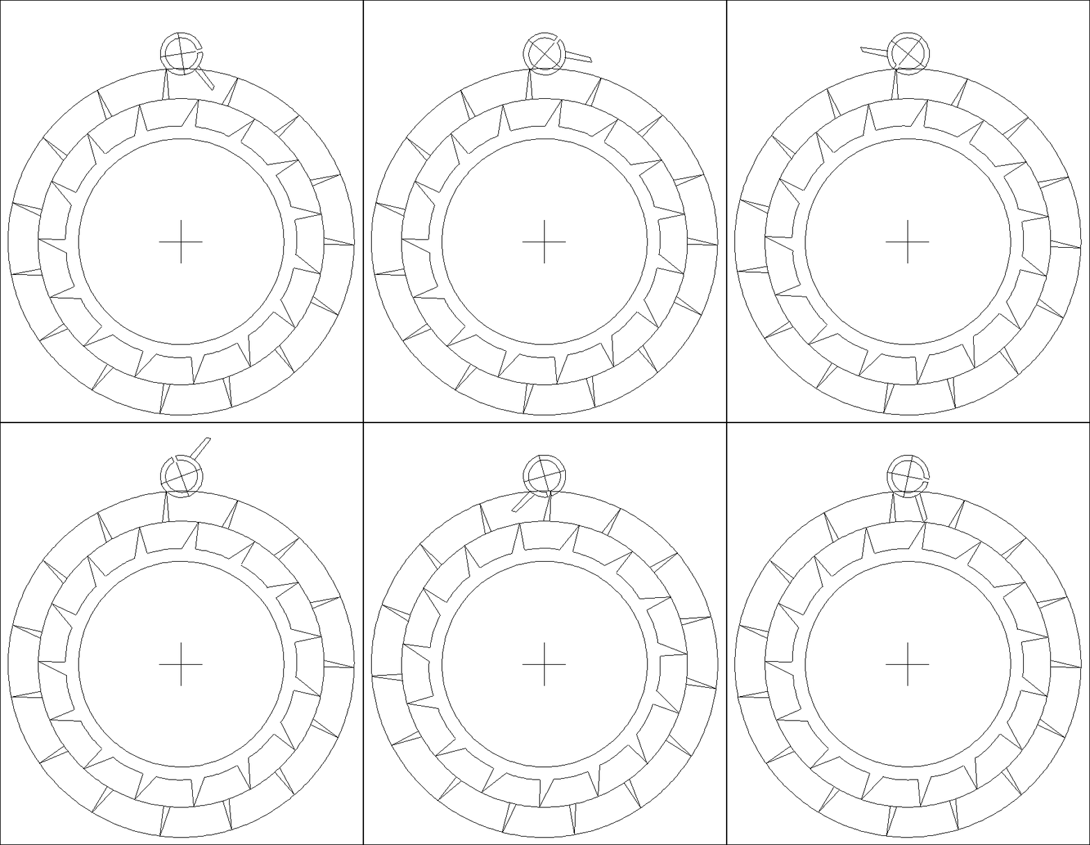
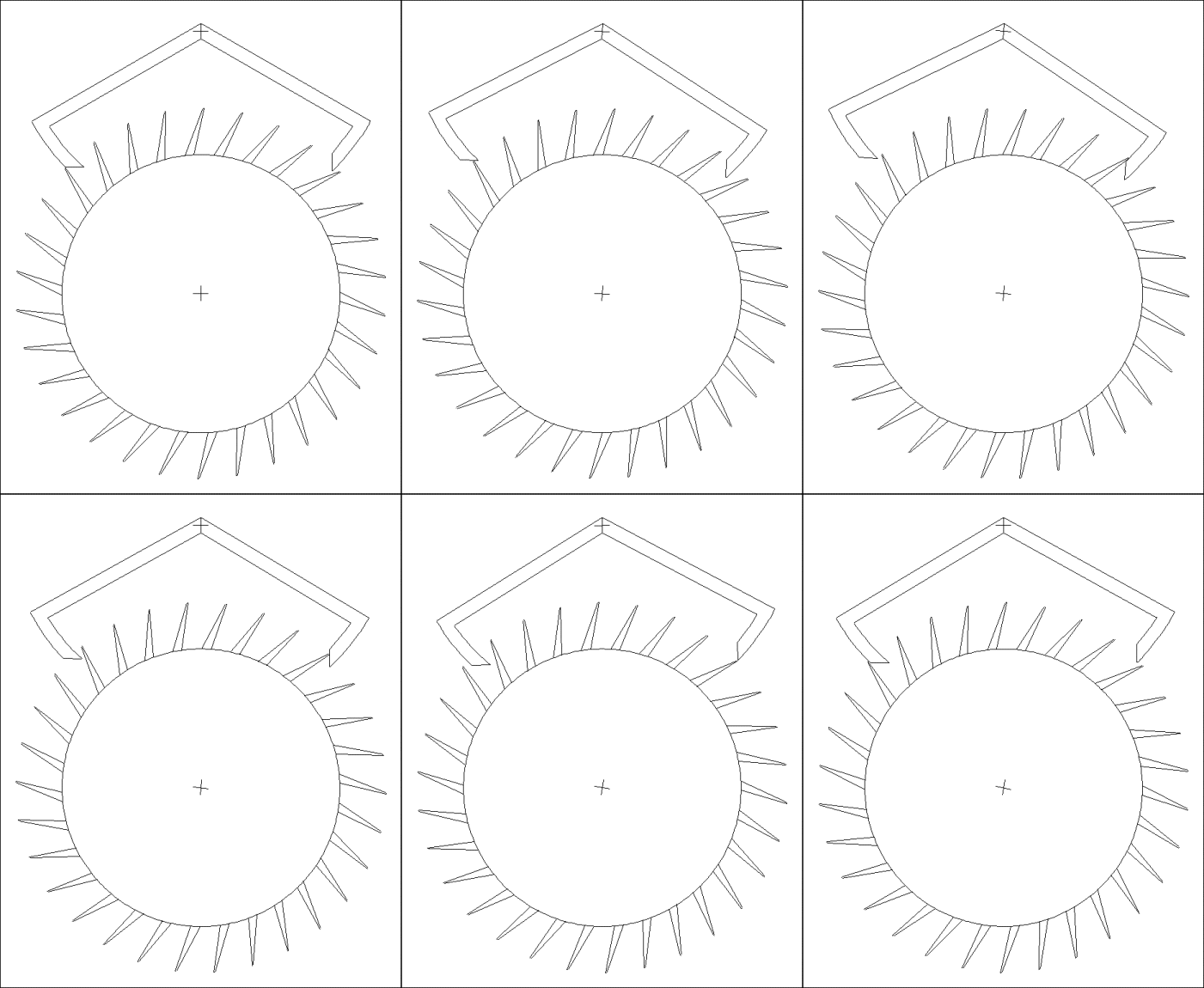
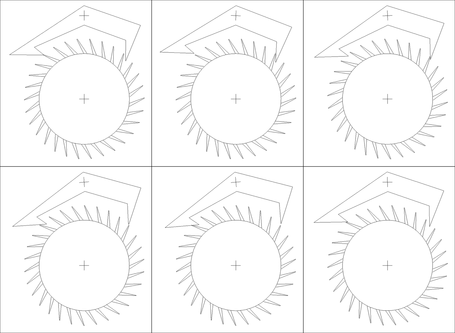
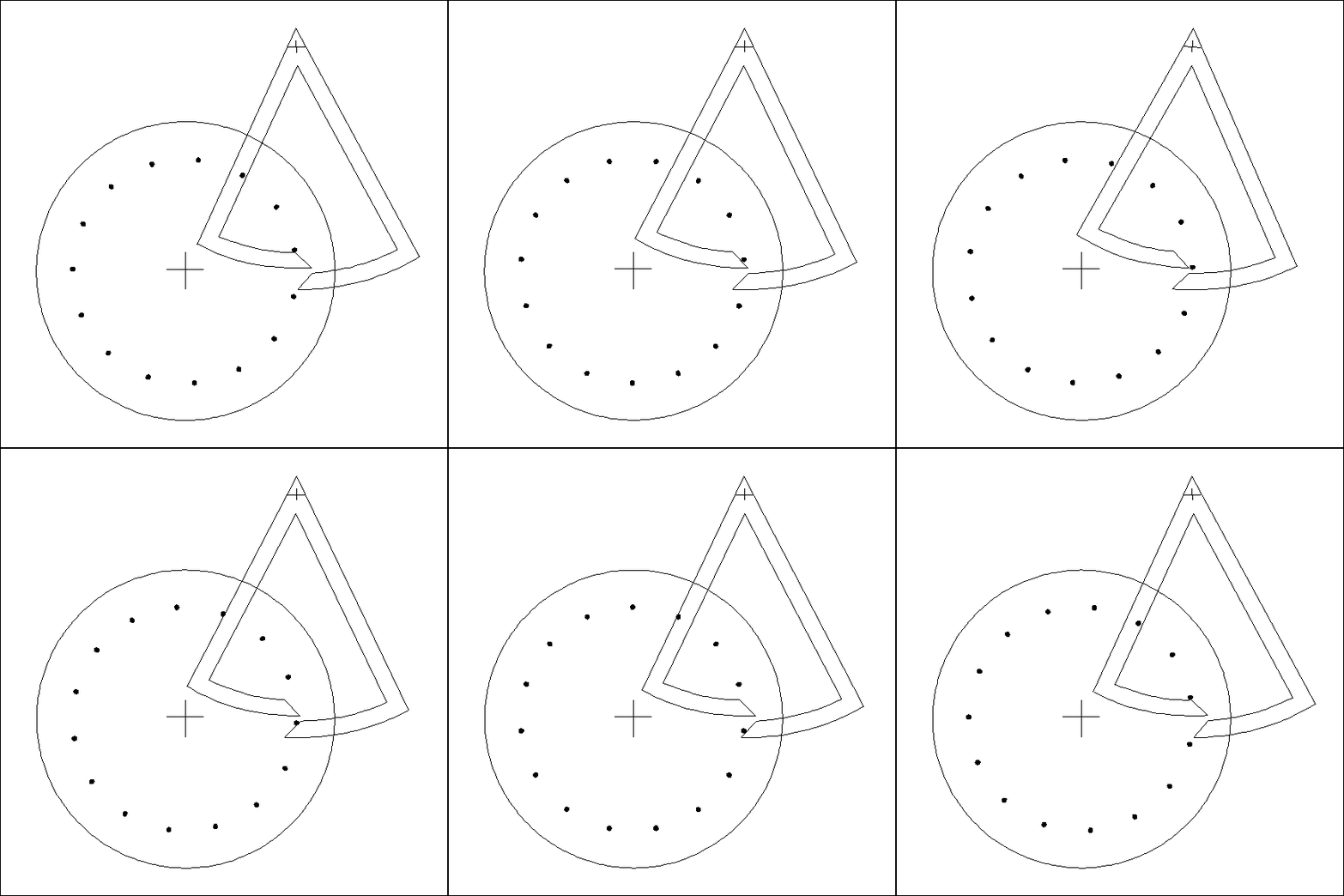
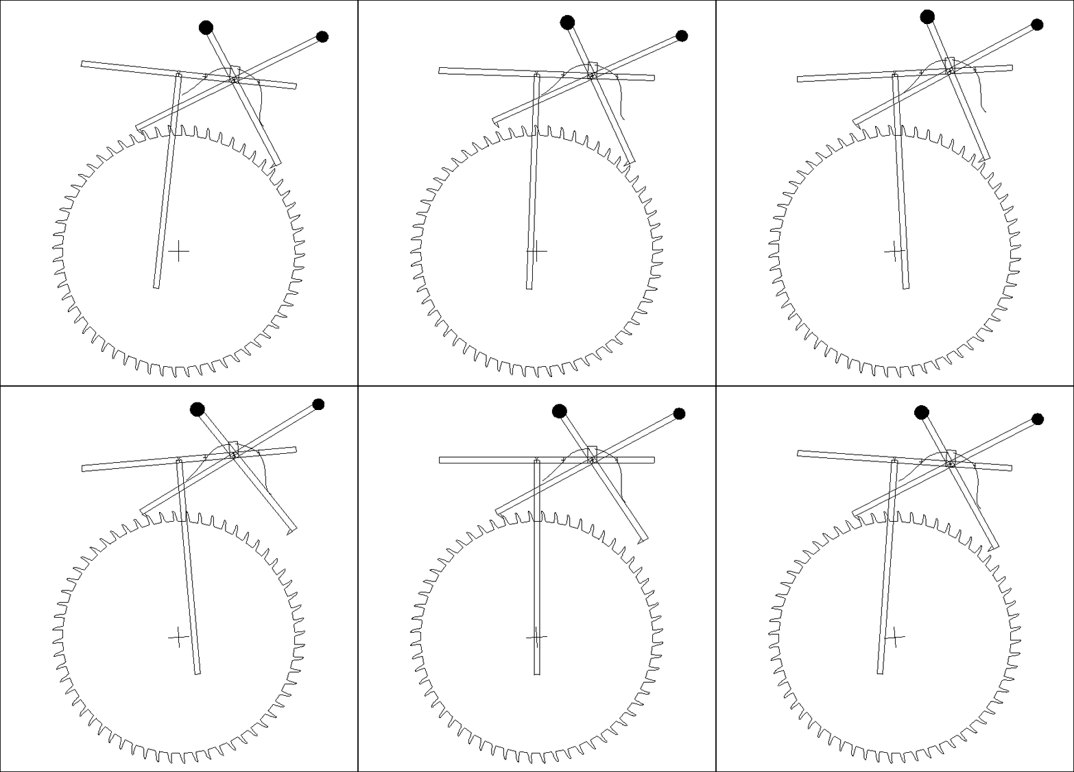
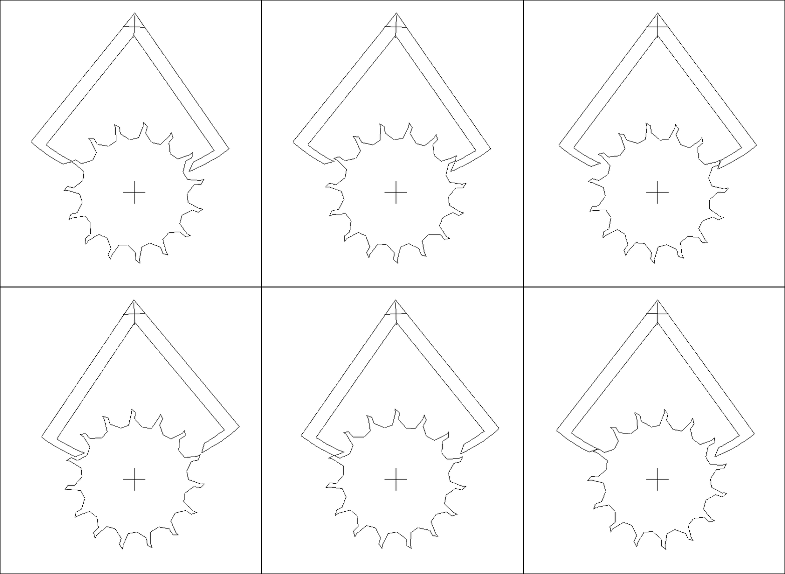
This is a modified Graham-style clock escapement with a fifteen-tooth escape wheel. The escape teeth have impulse faces that create lock (two degrees), like a club-tooth escape wheel in a Swiss lever watch escapement, and have a span of four degrees each. This design allows the pallets to be designed as symmetrically as possible. The pallets have curved (equidistant) locking faces to prevent recoil, and a span of six degrees each. There are therefore two degrees of drop on each side. The impulse face angle of each pallet is forty-five degrees, which is ideal. The escape wheel has been designed so that the escapement could have a self-adjusting beat feature, found in modern clocks. The pendulum has an amplitude of oscillation of ten degrees from one side to the other.
|
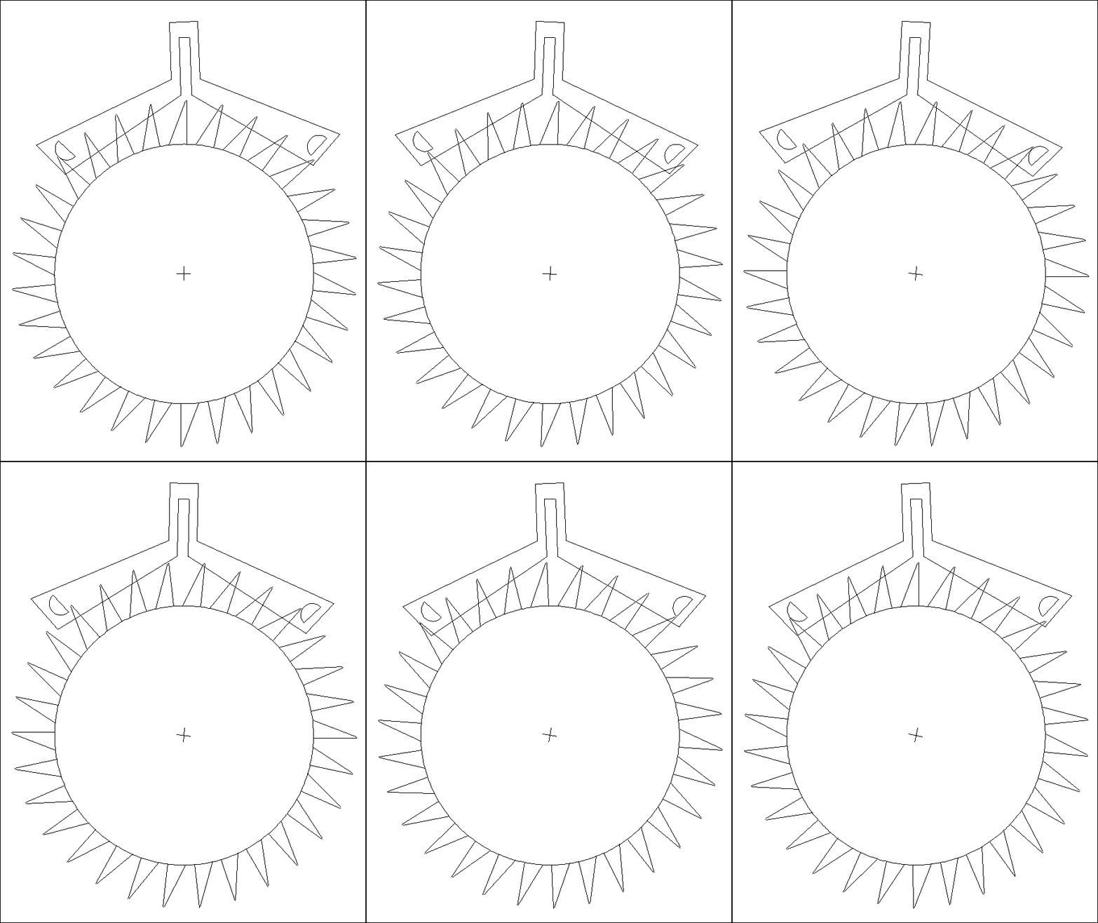
This escapement has the same pallets as the first modified Graham escapement on this website. The only difference is that the escape wheel has been replaced with a pin wheel that has 15 semi-circular pins (of the same shape as Brocot pallets).
|
Clock Buying Tips
Gearing: Introduction
Gearing: The Cycloidal Curve
Gearing: The Epicycloidal Curve
Gearing: The Involute Curve
Gearing: The Module and Gear Cutters
Gearing: Photos
Jaeger Le Coultre Atmos Clock
Atmos Clock Timekeeping
Atmos Clock Bellows
Clock Bushings Repair
More Clock Bushings Repair
Clock Pivots
Recycling Ammoniated Clock Cleaning Solution
Cleaning and Polishing Brass
The Modern Russian Submarine Clock
The Modern Russian Chronometer Clock
Mainsprings
Misc. Clock Repair Notes
Determining Pendulum Length
Repairing the Strike Rack Mechanism
Clock and Watch Lubrication
How lubricants Work
After the Lubricants Fail: Wear
Clock Repair Tools
Modern Grandfather Clock Weights
Setting Up a Herschede Tubular Bell Hall Clock
Herschede Grandfather Clock
History of the Herschede Hall Clock Co.
Herschede - Revere Clocks
The Revere Telechron Electric Clock Motor
Western Union Clock
Schatz Anniversary Clock
Schatz Royal Mariner Clock
Chelsea Ship's Bell Clock
Japy French Clock
French Carriage Clock
The Suspension Spring
A Modern Grandfather Clock
Watch Repair Notes
The Watch Balance Staff
Watch Construction
|
Daniel's Double Wheel Watch Escapement
Daniel's Coaxial Watch Escapement
Swiss Lever Watch Escapement
English Lever Watch Escapement
Cylinder Watch Escapement
Duplex Watch Escapement
Chronometer Clock (or Watch) Escapement
Graham Clock Escapement
Recoil Clock Escapement
Brocot Clock Escapement
Pin Wheel Clock Escapement
Gravity Clock Escapement
Grasshopper Clock Escapement
A Modified Clock Escapement
Another Modified Clock Escapement
Clock and Watch
Escapement Mechanics
The Origin and Evolution of
the Anchor Clock Escapement
Clock Links Page
Watch Links Page
Other Links Page
Tributes Page |
|
 |
| Clock Index |
|
|
To all Visitors
This site has been developed not just to sell Antiques and Collectibles (of course it does some of that) rather it is to provide information about Antiques, Collectibles, artwork, art pottery, furniture types, furniture styles, jewelry, and militaria from the Revolutionary War to the Vietnam War. This site is all about information and history that is not readily available elsewhere on the Internet. We think West St Paul Antiques is one of the best Antique Malls in the State of Minnesota and we have been working hard to create that excellence for the last 12 years. We have expertise on Antiques & Collectibles and as we read and study about history and antiques we also strive to be historians. We will share that expertise with you and all the visitors to our site. Stop by and visit our Antique Mall in West St Paul, Minnesota. Or, you are all welcome to visit us on the web.
This is a new website for us at West St Paul Antiques. We hope you enjoy the site. Please feel free to email me directly at floydruggles@weststpaulantiques.com if you have any questions or feedback about this site. Please sign our guest book and check out our Poetry Coffee Cup Cafe, or the Out and About Gallery. The Reference Library an all 5 Museums are open to you 24/7 on this website. Stop by one of the 1st Recon Battalion pages where you can read about my experiences in Vietnam. Oh, by the way, also check out all our Antiques, Collectibles, artwork, art pottery, clocks, mall specials, furniture types and styles, jewelry and militaria items for sale on this site and in our Antique Mall. Check it out by going to Antique Mall Tour. This site will be totally commercial free with no fees to pay. I'll be working on this site over time so bear with me. It should be finished by the end of 2010 with over 500 pages at that time and 900 pages by the end of next year.
Click here to go to our web Site Map and Categories.
|
Click a NEW link
To browse our Home page, Look over our Museums, 1st Reconnaissance Battalion pages, Recon Photo Gallery,
Out and About Gallery, Poetry Coffee Cup Cafe, About Us, Christmas Index, Antique Mall Tour,
Antiques & Collectibles, Furniture, Jewelry, Art Pottery, Artwork, Militaria,Contact Us, Hours and Directions,
Dealers pages, Consignment, Ebay Store, Translate this Website, Our Blogs, Books, Bottles & Jars, China, Crystal & Glass,
No Man Left Behind, Who Was Really the First President of the United States, Halloween pages, Primitives, Antique Photos,
The Day Eagle Cried, Financial Tip of the Year & Remembering The 50's & 60's Music Index.
or
Go to the top of each page of our website for the menu bar of categories. You will see a drop down menu appear for each category. Click a link to browse or click our
Site Map and Categories to find your link.
|
|
 |
| Me with your feedback on how I can Improve this website. |
|
| |
|
